For some time now I had been considering the possibility of fabricating a hidden track connection between two baseboards, one that would replace the present club style of copper clad veroboard with solder blobs to hold the track in place. It struck me that without too much effort it would be possible to produce a reliable hidden alternative using nothing other than a cordless drill, a paper clip and some cunning thinking.
Stage one of the operation requires you to drill a couple of holes horizontally into the thickness of the baseboard or it’s top framework, that coincide with the tracks rail alignment. This hole needs to be long enough to reach the track at the point where a soldered joint can be made to a drop wire, but the maximum hole length is determined by the physical length of the drill bit you can use. The hole does not have to be completely horizontal and in fact it is better to have it running “slightly uphill” from the horizontal, as this will aid you with the wire insertion later on. As for hole size it’s really your own choice of diameter as the wire will terminate on the edge of the board and be connected to a contact point, so the diameter of the hole should reflect your choice of termination (this will become clearer at the end of the article).
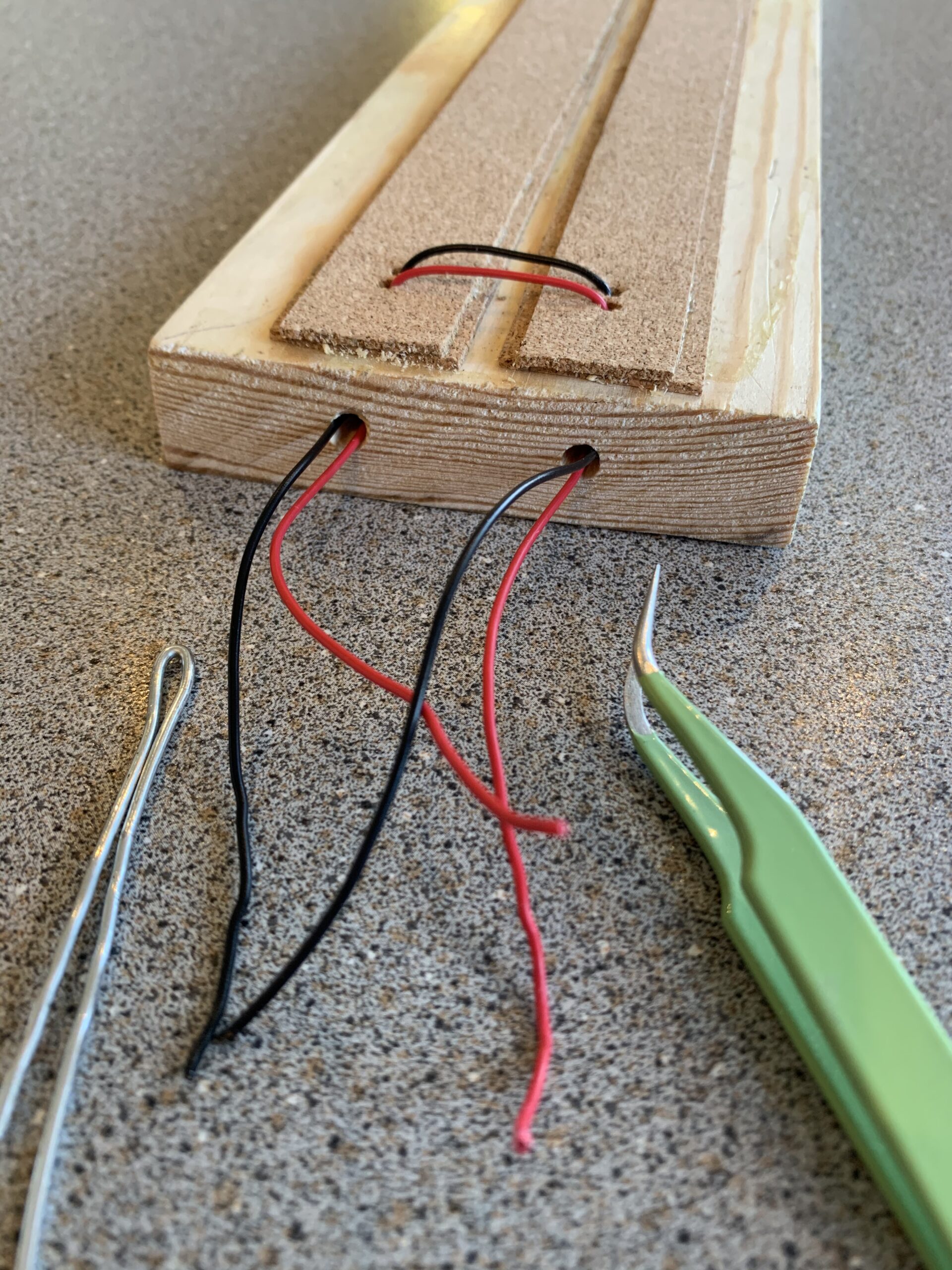
Stage two then requires you to drill another pair of holes in the top surface of the baseboard which will run at about 45 degrees to the vertical, but only made deep enough to make contact with the horizontal holes you have just drilled, these holes however, will only need to be wide enough to accept the drop wires and ideally, should match the diameter of the drop wires being used, as this will help you disguise them at the track ballasting stage.
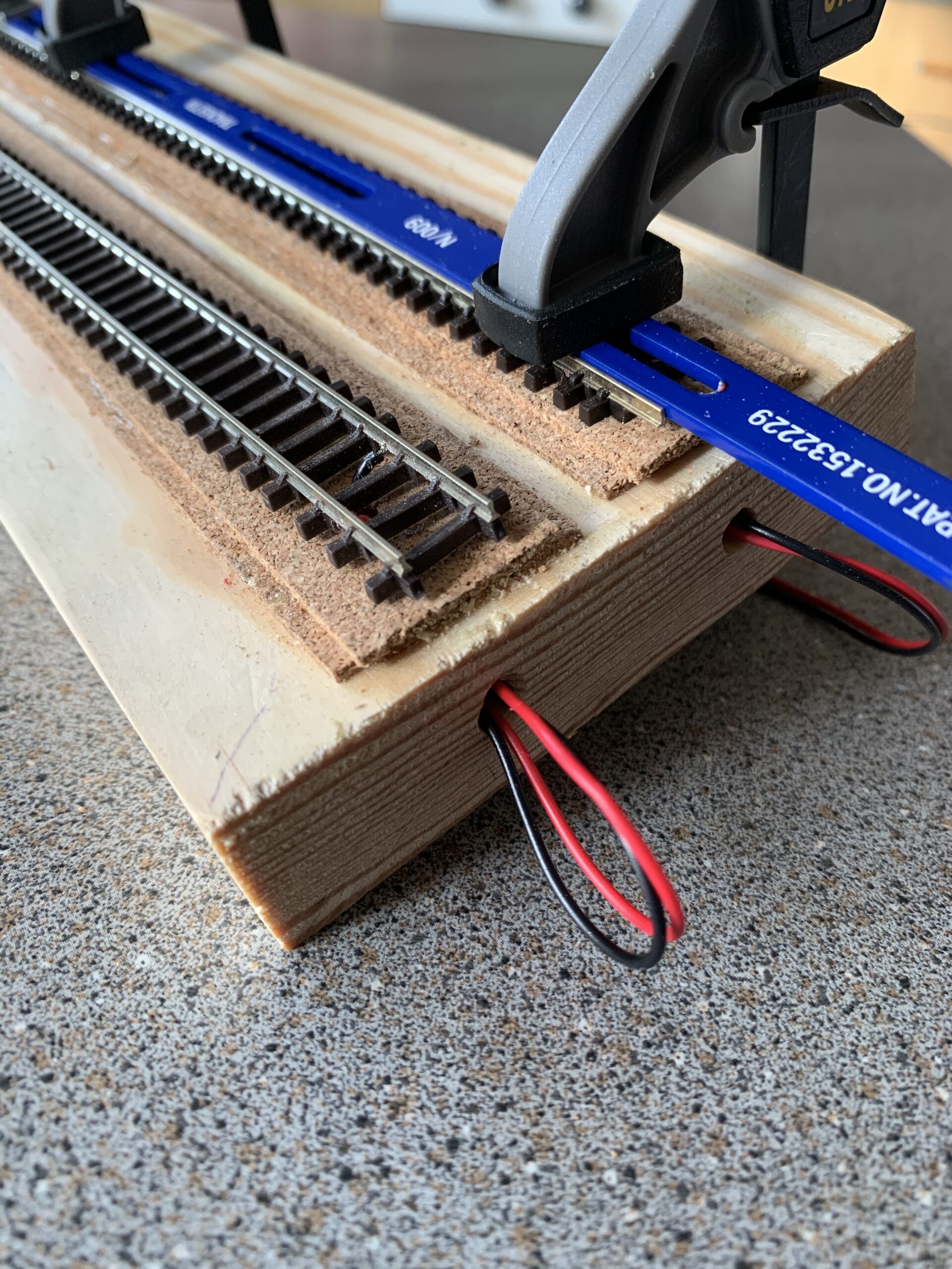
Stage three is where the fun begins, as it’s now time to insert the wires into the holes. With the top holes being the same diameter as the wires and at 45 degrees to the vertical, it is just a case of threading the wires down the holes gently until you feel some resistance, careful wiggling of the wire should help you locate the bottom of the horizontal hole and locating it will be obvious by the feeling of pushing the wire and it disappearing down the hole. Keep up steady but moderate pressure and you should be rewarded with the sight of the wire coming out of the end of the horizontal hole at the edge of the board. Cut the wire at each end leaving a longish tail of about 4 inches at both the entry and exit points as this will give some valuable working room when soldering up the track drop wires. If you encounter some difficulty in getting the wire through the horizontal hole, then an opened out paper clip or piece of stiff wire can be utilised to make a long grab wire with a short loop or hook on the end of it that can be inserted into the hole to a point where it is aligned with the vertical hole. With the drop wire in one hand and the grab wire in the other it’s a case of jiggling the two gently to establish contact and when you feel this contact a slight pull on the grab wire should be enough to pull the drop wire along the horizontal hole at which point you can begin to push the wire out on it’s own.
Stage four demands a connection be made with the rails on the track, and in the diagrams shown here I am using proprietary off the shelf N Gauge track so decided to solder the wires to the bottom face of the rail. Take your time with this operation on both rails as it will pay you to achieve as neat a finish as you can in order to properly mask the joint with ballast and paint later on.
The diagrams show what a neat compact finish can be achieved (depicted in N Gauge here) and there is no trace of unsightly joins, solder blobs or copper board that need to be disguised with paint and weathering.