The Club has traditionally been known for having an O Gauge Layout of some size, but as we have just moved into a new Clubroom, the original layout has had to be dismantled for transit, packed and stored, so we are in the process of reviewing what format this layout should take in the new, larger Clubroom.
The new working area for the layout (approximately 40 square feet) is considerably larger than the space we had available in the old Clubroom, and this has meant a complete revision of the track plan and layout facilities that we can offer to members on a new O Gauge Layout. This is likely to take quite a while to complete so please watch this space for any updates as and when they occur.
In the meantime here are a couple of interesting articles relating to O Gauge modelling projects undertaken by Club Members that may help you if you have come across a similar problem yourself whilst modelling and upgrading your locomotives.
PROJECT – DCC Conversion of a Heljan Class 37
The following article has been produced as a step by step guide to adding a DCC Sound module to an O Gauge Class 37 Diesel locomotive manufactured by Heljan. It aims to show how a methodical approach to the wiring conversion can really help to improve and supplement the various functions that can be applied to this Diesel Icon whilst using an ESU Loksound V4 or V5 XL Decoder. The many functions available to you with this Chip enable you to produce a model of great personal satisfaction as well as generate interest at shows and exhibitions.
1. Repurposing the existing Heljan wiring
The supplied Heljan wiring within the locomotive is to be repurposed into the ESU Decoder. It has been factory wired in a way that does not necessarily correspond to the known specification of wiring standards found in the UK and other areas of the world, however by a process of observation and elimination it is possible to trace the wiring back to it’s core function and combined/common connections before you continue to connect anything to the DCC Chip.
It became obvious to me during this process, that a clear labelling and identification system would pay handsomely later on when any connections were to be made to the Chip interface, so I adopted a method of pinning out the wires for each set of command functions and labelling them accordingly so that they could be quickly connected later on to the screw terminal block on the Chip.
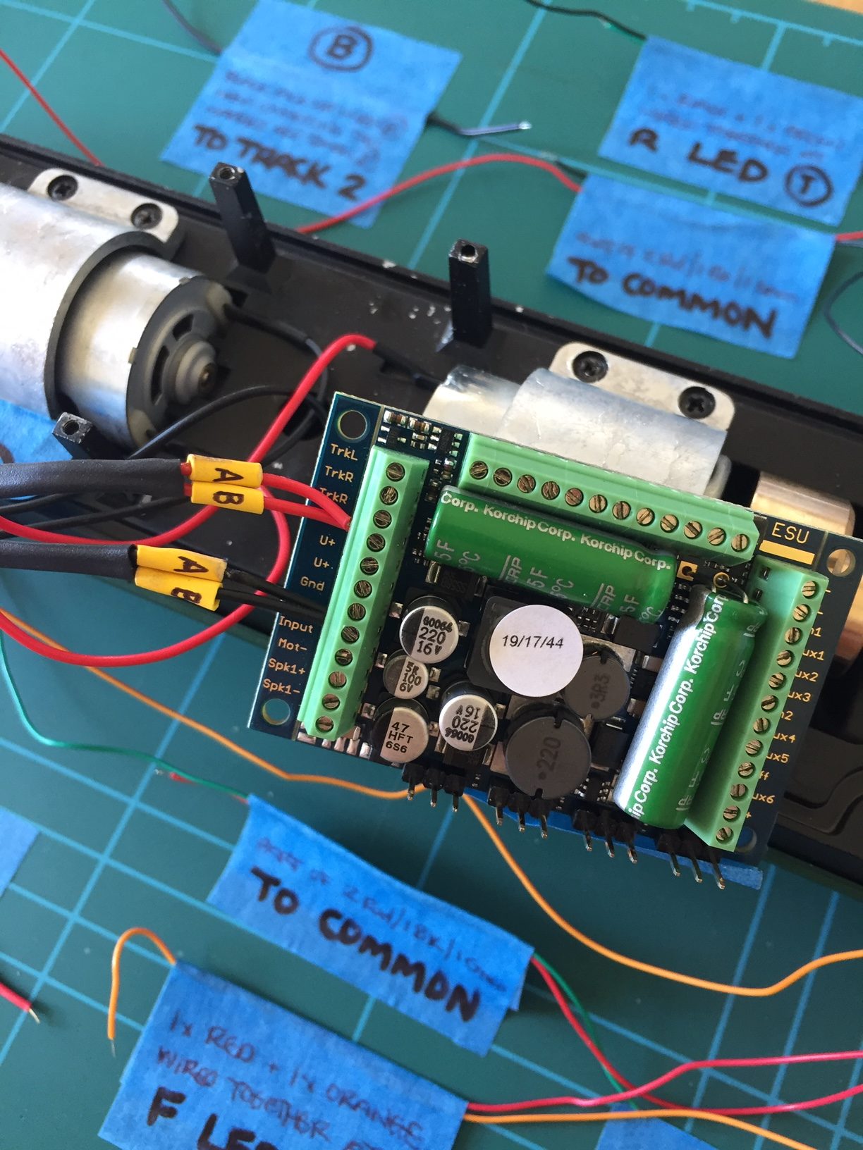
PIC 1 – Showing the identification system in operation (and for those of us who can remember it, reminds me of those days spent in a school Biology Class) with everything spread out in its relevant position, grouped, labelled and secured to the cutting matt to aid identification.